
Table of Contents
- Where Flanged Joints Sit in a Data Center Cooling System
- Cooling Circuits That Use Flanged Pipe Connections
- Flange Types We Manufacture for Cooling Pipework
- Flange Standards Specified on Data Center Projects
- Flange Materials and Grades for Coolant Service
- Pressure Class, Face Type and Size Selection
- Gaskets, Bolting and Torque for Leak-Free Joints
- Flanged Joints Compared With Grooved Couplings and Welded Joints
- Leak Prevention and Maintenance at Flanged Connections
- Welding, Cleaning and Passivation Before the Loop Goes Live
- Testing, Documentation and Certification Buyers Ask For
- How to Specify and Order Flanges for a Cooling Project
- Our Supply Scope for Data Center Cooling Projects
- Frequently Asked Questions About Data Center Cooling Flanges
Flanges for data center cooling systems carry the bolted joints on chilled water headers, condenser water circuits, facility water branches and the coolant loops inside a CDU. Kalikund Steel & Engineering Co. forges and machines fittings and flanges at our works, using billets, rounds and pipe from established primary mills. We manufacture to A181, A182, A350, A403 and A420, along with BS, DIN, JIS and IS drilling. Every item leaves with an EN 10204 3.1 mill test certificate as standard, and we hold our own heat treatment, machining and inspection in house.
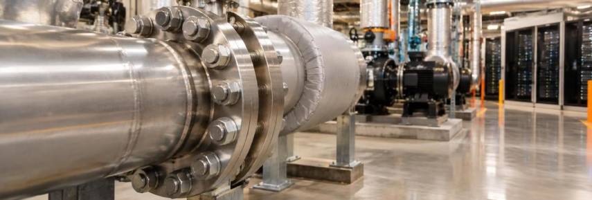
Where Flanged Joints Sit in a Data Center Cooling System
A flange is the planned disassembly point in a cooling loop. Welded joints are permanent. A bolted flange is one that a contractor can open again for inspection, cleaning or replacement, which is why it lands at every equipment interface on the floor.
Flanged Connections on the Chilled Water Loop
Chilled water flanges appear wherever the loop must be opened a second time. Chiller nozzles, primary pump suction and discharge, header tie-ins, strainer bodies, butterfly valve bodies, CRAH coil connections, air separators and expansion tanks all take bolted joints. The welded sections between them stay closed for the life of the building. Flanged joints in chilled water piping are what make the rest of the loop serviceable.
Facility Water, Condenser Water and Technology Cooling Loops
Liquid cooling splits the water into three circuits. The condenser water system (CWS) rejects heat outdoors. The facility water system (FWS) feeds the white space. The technology cooling system (TCS) runs inside the coolant distribution unit and out to the cold plates. A CDU creates an isolated secondary loop from the facility supply, and it controls that loop's pressure, temperature, flow rate and filtration. It also holds the secondary supply temperature above dew point so the pipework does not sweat.
The CDU’s heat exchanger is the barrier between the FWS and the TCS, and the CDU flange connections are where both loops join the unit. Branch piping, isolation valves and strainers between the facility header and the CDU inlet are flanged, because that interface gets commissioned, flushed and reopened more than any other. Flange connections in liquid cooling loops are therefore a serviceability decision before they are a pressure decision.
How Rising Rack Density Changed the Flange Specification
Rack power has moved far past what air alone can carry. Air cooling handles roughly 30 to 40 kW per rack. Current AI racks run at 120 to 140 kW, and the next generation is expected to pass 200 kW. All of that heat has to leave through liquid.
More heat means more flow. More flow means larger headers, more CDUs and far more connection points per floor. Flange count, size and serviceability now sit on the critical path of a build programme.
ASHRAE TC 9.9 defines the facility water classes that set the supply temperature these loops run at. The fifth edition of the Thermal Guidelines renamed the classes by their upper temperature limit.
| Current class | Facility water supply temperature | Former designation |
|---|---|---|
| W17 | 2-17 °C | W1 |
| W27 | 2-27 °C | W2 |
| W32 | 2-32 °C | W3 |
| W40 | 2-40 °C | New class |
| W45 | 2-45 °C | W4 |
| W+ | Above 45 °C | W5 |
Uptime Institute (2026) reports facility water typically at 16 to 22 °C, and expects dedicated liquid cooling loops to step up to about 26 to 29 °C. GB200 and GB300 systems accept inlet water up to 45 °C, though most operators run cooler.
Cooling Circuits That Use Flanged Pipe Connections
Six circuits on a data center site carry flanged pipe connections. They are the chilled water mains, the facility water branch to each CDU, and the condenser water and cooling tower loop. The air-side coil tie-ins, the manifolds inside the technology cooling system, and the make-up water and drain lines complete the list. Each one uses a different size band and a different grade.
| Cooling loop | Typical line size | Flange type used | Usual class | Usual material |
|---|---|---|---|---|
| Chilled water header and risers | 200 to 900 NB | Weld neck, blind | Class 150, Class 300 on tall risers | Carbon steel or SS 304L |
| Chilled water branch to CRAH | 50 to 150 NB | Slip-on, weld neck | Class 150 | SS 304L |
| Condenser water and cooling tower circuit | 150 to 600 NB | Weld neck, lap joint | Class 150 | SS 316L or duplex 2205 |
| Facility water branch to CDU | 50 to 200 NB | Weld neck, slip-on, blind | Class 150 | SS 316L |
| TCS inside the CDU skid | 25 to 100 NB | Weld neck, lap joint | Class 150, Class 300; orifice flanges to ASME B16.36, Class 300 minimum | SS 316L |
| Make-up water and drain lines | 15 to 50 NB | Socket weld, threaded | Class 150 | SS 304L or SS 316L |
Chilled Water Headers, Risers and Distribution Mains
The largest flanges on any data center site sit on the chilled water mains. Headers and risers run from 200 NB up to 900 NB and larger on campus builds. Every valve, branch, strainer and equipment nozzle on that run is a bolted joint. Size is what decides the standard here. Above NPS 24 the drilling question moves away from ASME B16.5, and the choice between large diameter series and waterworks drilling is settled at design stage rather than on site.
Facility Water System to CDU Connections
Each CDU takes a branch off the facility header. That branch carries an isolation valve, a strainer, a balancing valve, a flexible hose and then the CDU nozzle itself. Contractually this last stretch often falls between two scopes, so it gets opened and reworked more than any other joint on the floor. Serviceable bolted connections matter more here than anywhere else in the building.
Condenser Water and Cooling Tower Circuits
Open-circuit water changes the material argument completely. Make-up water chemistry concentrates as water evaporates, chlorides build up, and biological fouling adds a second attack mechanism. Cooling tower pipe flanges are where stainless steel earns its cost over carbon steel. Pitting on an open circuit is a maintenance cost that repeats every year.
CRAH, Fan Wall and Rear Door Heat Exchanger Tie-Ins
Air cooling has not disappeared from a liquid-cooled hall. In current AI racks, roughly 85 to 90% of the heat goes to liquid, and the rest still leaves by air. That remaining load keeps CRAH units, fan walls and rear door heat exchangers in the design. Their coil connections are small-bore flanged or grooved branches, usually 50 NB to 150 NB.
Direct-to-Chip Manifolds and Heat Recovery Returns
Inside the technology cooling system, the pipework is mostly stainless tube and fittings. Flanged interfaces appear at pumps, heat exchangers, filter housings and skid boundaries. Warm-water direct-to-chip loops return water hot enough to be worth reusing, and heat recovery into district heating or process water is now a live design item on some campuses. A higher return temperature changes the gasket choice and the thermal movement allowance compared with a chilled loop.
Flange Types We Manufacture for Cooling Pipework
Seven flange types cover almost every joint on a cooling system: weld neck, slip-on, blind, lap joint with stub end, socket weld, threaded and orifice. A flange adaptor handles the eighth case, where grooved pipework meets a flanged equipment nozzle.
| Flange type | How it joins the pipe | Best use in a cooling system | Confirm before ordering |
|---|---|---|---|
| Weld neck | Butt weld to a tapered hub | Main headers, pump discharge, thermal cycling | Bore must match the pipe schedule |
| Slip-on | Slides over pipe, double fillet weld | Class 150 chilled and condenser water runs | Lower fatigue strength than weld neck |
| Blind | Bolted cap, no bore | Capped tap-off points, test and flush points | Thickness rises with class and size |
| Lap joint with stub end | Flange rotates on a welded stub end | Long stainless headers, awkward bolt alignment | Only the stub end needs to be the wetted alloy |
| Socket weld | Pipe seats in a socket, fillet weld | 15 NB to 80 NB drains, vents, instrument tappings | ASME B16.5 limit is NPS 3 (80 NB), NPS 2½ in Class 1500 |
| Threaded | Screwed connection | Small bore gauge and sensor points | Not for vibration or thermal cycling |
| Orifice | Paired flanges with pressure tappings | Flow metering per CDU or per zone | Supplied as a pair with jack screws |
| Flange adaptor | Bolts a grooved pipe end to a flange | Grooved mechanical rooms meeting flanged equipment | Gasket and coupling rating must match |
Weld Neck Flanges for Main Cooling Headers
Weld neck flanges carry a tapered hub that is butt-welded to the pipe. That hub spreads bending stress into the pipe wall instead of concentrating it at the weld. On main chilled water headers, weld neck flanges handle thermal cycling and pump vibration better than any other type. One ordering point matters: the bore is machined to a stated pipe schedule, so the schedule has to be on the purchase order.
Slip-On Flanges for Low Pressure Water Lines
This type slides over the pipe end and takes a fillet weld inside and outside. Fabrication is quicker and cut length is more forgiving. On Class 150 condenser water runs away from pump discharge and thermal movement, slip-on flanges keep fabrication cost down at an acceptable trade-off. The penalty is fatigue life, roughly one third that of a weld neck, so on headers that see pump vibration or real thermal cycling the weld neck remains the right choice.
Blind Flanges for Future Tap-Off Points
A blind flange caps a connection that is not in use yet. Open Compute Project guidance recommends preserving pipe paths and tap-off connection points to the facility water system, so that liquid cooling can be added later in a facility's life cycle. Capped tap-off points on a facility water header use blind flanges for exactly that reason. A future block of liquid-cooled racks can then be tied in without draining the loop.
Lap Joint Flanges and Stub Ends for Stainless Loops
The flange on a lap joint assembly rotates freely on a stub end. Only the stub end touches the water, so only the stub end needs to be the specified alloy. On long stainless headers, lap joint flanges let bolt holes be rotated into line during fit-up, and they hold the alloy spend down on a long run.
Socket Weld, Threaded and Orifice Flanges
Small-bore work around CDUs and pump sets uses socket weld and threaded flanges. ASME B16.5 covers socket weld flanges from NPS 1/2 to NPS 3, which is 15 NB to 80 NB, and most cooling work sits at the lower end of that. Drain lines, vent lines, gauge points and instrument tappings all fall in this band. Where flow per CDU or per zone is metered for thermal commissioning and PUE reporting, orifice flanges carry the plate and the pressure tappings as one assembly.
Flange Adaptors for Grooved Piping
Many data center mechanical rooms are grooved throughout. A flange adaptor lets a grooved pipe end bolt straight to a flanged pump, valve or chiller nozzle. Both systems then coexist on one site without a transition spool.
Flange Standards Specified on Data Center Projects
Four standard families cover almost all data center cooling work. ASME B16.5 and ASME B16.47 govern steel pipe flanges, and AWWA C207 and AWWA C228 govern waterworks-style ring flanges. EN 1092-1 covers European and GCC drawings, and IS 6392 covers Indian project specifications.
| Standard | Size range | Pressure designation | Flange types covered | Where it is used on a data center job |
|---|---|---|---|---|
| ASME B16.5 | NPS 1/2 to NPS 24 | Classes 150 to 2500 | Weld neck, slip-on, blind, lap joint, socket weld, threaded | Most cooling pipework |
| ASME B16.47 Series A | NPS 26 to NPS 60 | Classes 150 to 900 | Weld neck, blind | Large campus chilled water headers |
| ASME B16.47 Series B | NPS 26 to NPS 60 | Classes 75 to 900 | Weld neck, blind | Large headers where a compact flange is specified |
| AWWA C207 | 4 in to 144 in | Classes B, D, E, F by psi | Ring, hub, blind, in carbon steel | Campus mains and make-up water |
| AWWA C228 | 2 in to 72 in | Classes SA to SF by psi | Ring and blind, in stainless | Stainless campus mains and corrosive water service |
| EN 1092-1 | DN 10 to DN 4000 | PN 2.5 to PN 400 (PN 6 to PN 40 in cooling work) | Types 01, 02, 05, 11 and others | European and GCC drawings |
| IS 6392 | As per table | By class | Slip-on, weld neck, blind | Indian project specifications |
ASME B16.5 for NPS 1/2 Through NPS 24
ASME B16.5 flanges for cooling water cover pipe flanges and flanged fittings from NPS 1/2 through NPS 24, in Classes 150, 300, 400, 600, 900, 1500 and 2500. Chilled water uses Class 150 and Class 300 almost exclusively. The standard also fixes the facings, the pressure-temperature rating tables and the forged material specifications under ASTM A182. NPS 24 is a hard ceiling, and that ceiling is what brings the next standard into the drawing.
ASME B16.47 Series A and Series B for Large Diameter Headers
ASME B16.47 covers large diameter steel flanges from NPS 26 through NPS 60 for weld neck and blind flanges. Series A runs Class 150 to Class 900. Series B adds Class 75 below that, so Class 75 is available in Series B only. Above NPS 24, ASME B16.47 flanges take over on large campus headers. The standard holds two series with separate lineages: ASME B16.47 Series A descends from MSS SP-44, and ASME B16.47 Series B descends from API 605.
The two series are not interchangeable. ASME B16.47 Series A flanges are heavier and thicker than ASME B16.47 Series B at the same size and class. Series A carries a larger bolt circle and uses fewer, larger bolts. Series B uses more, smaller bolts on a smaller bolt circle. At NPS 36 Class 150, Series A has 32 bolt holes and Series B has 44. Confirm the exact drilling against the governing edition of the standard and against the mating equipment flange before release. Both series share the same pressure-temperature rating tables as ASME B16.5, which means the rating is independent of size.
AWWA C207 and AWWA C228 for Waterworks-Style Flanges
AWWA C207 covers carbon steel waterworks flanges from 4 in to 144 in. AWWA C228 covers stainless steel flanges from 2 in to 72 in, usually in 304L or 316L. Both are rated in psi rather than by ASME class. AWWA C228 stainless steel flanges suit large campus cooling mains and make-up water lines, where the diameter is large and the pressure is low.
| Class | Material | Pressure rating | Bolt pattern |
|---|---|---|---|
| SA | Stainless | 50 psi | ASME Class 150 |
| B / SB | Carbon / stainless | 86 psi | ASME Class 150 |
| D / SD | Carbon / stainless | 175 psi, 150 psi at 14 in and larger | ASME Class 150 |
| E / SE | Carbon / stainless | 275 psi | ASME Class 150 |
| F / SF | Carbon / stainless | 300 psi | ASME Class 300 |
The practical value sits in that last column. AWWA ring flanges are drilled to the ASME B16.1 Class 125 cast iron pattern. In sizes 24 in and smaller that pattern also matches ASME B16.5 Class 150, so they bolt to standard Class 150 equipment flanges without an adaptor. Above 24 in, confirm the drilling against the mating equipment rather than assuming a Class 150 match. Class F and Class SF follow the B16.1 Class 250 / ASME Class 300 pattern instead.
EN 1092-1, DIN and Indian Standards
EN 1092-1 covers PN 2.5 through PN 400 and DN 10 through DN 4000, across about twelve flange types. Data center cooling work sits in a narrow part of that: PN 6, PN 10, PN 16, PN 25 and PN 40, in Types 01, 02, 05 and 11. Hyperscale clients, CDU manufacturers and GCC contractors often issue EN drawings while the local contractor works in ASME. DIN 2576 still appears on legacy drawings. PN and Class ratings never mix on one joint, because the drilling differs.
Indian projects commonly issue a hybrid specification. IS 6392 appears alongside BS 4504 and BS 10 Table F legacy drilling, and alongside a client standard specification. Drilling on those jobs should be confirmed against the mating equipment rather than assumed from the grade.
Flange Materials and Grades for Coolant Service
Grade selection follows the water. Five material families cover data center cooling: 304 and 304L, 316 and 316L, duplex and super duplex, the nickel and copper alloys, and titanium for heat rejection on seawater sites.
| Grade | Specification | Where it suits | Chloride tolerance | Relative cost |
|---|---|---|---|---|
| SS 304 / 304L | ASTM A182 F304, F304L | Treated closed-loop chilled water | Low | Lower |
| SS 316 / 316L | ASTM A182 F316, F316L | Coolant-wetted service, TCS, facility water | Moderate | Moderate |
| Duplex 2205 | UNS S31803, S32205 | Condenser water, higher make-up water chlorides | High | Higher |
| Super duplex 2507 | UNS S32750 | Coastal sites, concentrated circuits | Very high | Higher |
| Cupro-nickel 90/10 | Copper alloy | Seawater and brackish heat rejection | High in flowing seawater | Higher |
| Titanium Grade 2 | Titanium | Seawater heat exchangers | Very high | Higher |
Stainless Steel 304 and 304L Flanges
Grade 304L works where the chilled water is treated and the chloride level stays controlled. Closed loops with a managed inhibitor package fall into that category. The low carbon variant keeps carbide precipitation down after welding, which matters on a fabricated header. Treat 304L as the economy option on a closed circuit rather than the default across the site.
Stainless Steel 316 and 316L Flanges
Stainless steel 316 flanges are the working default for coolant-wetted service. Molybdenum raises resistance to chloride pitting. The L grade holds carbon low so the heat affected zone keeps its corrosion resistance after welding. SS 316L flanges for liquid cooling also match the fluid. Open Compute Project guidance and coolant manufacturer datasheets list stainless steel 304L, 316L or higher grades as acceptable wetted materials for PG25-class fluids. PG25 is nominally 25% propylene glycol with high-purity water and a corrosion inhibitor package, and it is the common single-phase heat transfer fluid in direct-to-chip loops.
The reason 316L became the standard TCS choice is worth stating plainly. OCP’s PG25 guideline lists 304L, 316L or higher grades as preferred wetted stainless steels. Many projects choose 316L because its molybdenum gives extra margin against chlorides. Corrosion testing for these fluids is carried out to ASTM D8040.
Duplex 2205 and Super Duplex 2507 Flanges
Where condenser water chlorides climb beyond what 316L comfortably handles, duplex steel flanges bring roughly double the yield strength and a higher pitting resistance equivalent number. That strength allows thinner sections, which keeps the weight of a large-diameter flange down. Super duplex 2507 extends the same argument to coastal sites and heavily concentrated circuits. PREN is the figure most buyers quote when comparing the two.
Nickel Alloy, Copper Alloy and Titanium Flanges
Seawater and brackish-water cooled sites move outside the stainless range altogether. Monel 400 flanges, Inconel 625, 90/10 cupro-nickel and titanium Grade 2 all appear on heat rejection circuits and specialist heat exchangers. Coolant guidance for PG25-class fluids advises avoiding Hastelloy B and other alloys designed for reducing environments.
Preventing Galvanic Corrosion Between Dissimilar Metals
A cooling loop mixes metals by design. Copper cold plates, aluminium components, stainless pipework and sometimes carbon steel all share one fluid. Dielectric isolation at the flange breaks the electrical path between them. An isolation kit consists of an isolating gasket, a full-length sleeve on every bolt, and phenolic and metal washers at both ends. Retainer materials such as G10, G11, phenolic and G7 cover different temperature ranges. The loop's full wetted materials list should go to the coolant supplier for sign-off before the order is placed.
Pressure Class, Face Type and Size Selection
Three decisions settle most of a flange schedule: the pressure class, the face type and the size band. Each one has a clear rule.
Choosing Between Class 150 and Class 300
Specify Class 150 for standard chilled water and condenser water service. Chilled water is a low-pressure, moderate-temperature duty, and Class 150 carries it comfortably. Move to Class 300 on tall risers and multi-storey campus builds, where static head plus pump head plus surge pressure adds up past the Class 150 rating. Rate the flange against the design pressure of the system, not the day-to-day operating pressure.
Raised Face or Flat Face in the Mechanical Room
Raised face is the ASME B16.5 default for steel flanges, with a standard raised face height of 1.6 mm (1/16 in) on Class 150 and Class 300. Use flat face wherever a steel flange bolts to a flat-faced cast iron pump, valve or vessel.
This is the most common field error in HVAC pipework, and the reason it keeps happening is that the drilling fits. ASME B16.1 cast iron Class 125 flanges historically allowed flat faces, and the Class 125 cast iron bolt pattern matches Class 150 steel drilling. The two parts bolt together, then the raised face acts as a fulcrum and cracks the cast iron hub. ASME B31.1 gives one answer with two routes to it. Either machine the raised face off the steel flange, or buy the steel companion flange flat-faced to begin with. In both cases a full-face gasket must be used, so the bolt load spreads across the whole face instead of leaving a gap under the bolt circle.
Flange Face Finish and Size Range
Face finish is specified as a serrated spiral or concentric finish within a stated Ra range. A spiral wound gasket needs a 3.2 to 6.3 µm Ra (125 to 250 µin) finish. Soft elastomer and sheet gaskets work on the same finish or a rougher one, because the soft material flows into the serrations. Size range across a data center runs from 15 NB instrument branches to 1200 NB campus mains, and the standards table above shows where each standard takes over.
Gaskets, Bolting and Torque for Leak-Free Joints
Buyers order gaskets and bolting with the flange, so all three belong on one line of the enquiry. Gasket material follows the fluid. Bolting follows the flange material. Torque follows a method.
EPDM resists water, steam and salt water, and it is the default elastomer for water and glycol-water service. Full face gaskets go on flat-face joints, ring gaskets on raised face. Inhibitor packages differ between coolant brands, so confirm the elastomer against the specific coolant datasheet. Warm-water and heat recovery loops ask for higher seating stress, and a spiral wound gasket with a stainless winding handles that duty. PTFE suits circuits that see chemical cleaning cycles.
Match the bolting to the flange material. ASTM A193 Grade B8 studs with ASTM A194 Grade 8 nuts suit 304 and 304L flanges. For 316 and 316L flanges, and for any chloride-bearing service, specify ASTM A193 Grade B8M studs with ASTM A194 Grade 8M nuts. Then tighten in four passes:
- Pass 1: Cross pattern to roughly one third of the target torque.
- Pass 2: Cross pattern to roughly two thirds of the target torque.
- Pass 3: Cross pattern to full torque.
- Pass 4: A final clockwise pass at full torque.
Over-torquing crushes or extrudes an elastomer gasket, and the joint then leaks for the reason the torque was meant to prevent. Order isolation kits for mixed-metal joints as a matched set rather than as loose parts.
Flanged Joints Compared With Grooved Couplings and Welded Joints
A working data center uses all three joining methods. Grooved couplings install faster, welded joints are permanent, and flanged joints own the equipment interfaces and anything that must be opened again.
| Criterion | Flanged joint | Grooved coupling | Welded joint |
|---|---|---|---|
| Installation speed | Slower | Fastest | Slowest |
| Hot work required | Only for the flange-to-pipe weld, usually done in the shop | No | Yes |
| Re-openable for service | Yes | Yes | No |
| Inspectable before pressurisation | No | No | Yes, by radiography or ultrasonics |
| Typical use in a data center | Equipment interfaces, large headers | Mechanical room runs | Permanent concealed runs |
| Large diameter suitability | Strong to NPS 60 and beyond | Good within coupling range | Strong |
| Vibration tolerance | Good with weld neck | Good with flexible couplings | Strong |
Manufacturer-reported installation data puts grooved mechanical couplings at roughly three times faster to install than flanged joints, and about five times faster than welded joints, with no hot work. That is a real advantage in a mechanical room. The honest limitation on the flange side is inspection. A flanged joint cannot be checked without filling and pressurising the system, while a weld can be radiographed or ultrasonically tested before the loop is wet. Flanges answer that limitation with detection rather than with inspection.
Leak Prevention and Maintenance at Flanged Connections
Water near live IT equipment is the central anxiety on a liquid-cooled floor. Four controls address it.
- Detection at the joint: Open Compute Project guidance recommends leak detection for threaded, flanged, crimped and fused connections, and it recommends placing those connections where severity risk is low and detection is available. Rope sensors along the header, point sensors under equipment nozzles and pressure-drop alerting at CDUs make up the usual set.
- Condensation control: Chilled water below dew point makes the pipe sweat, and a flange is a break in the insulation line. Removable insulation jackets cover the joint and maintain the vapour barrier, while still allowing the bolts to be reached at a shutdown.
- Re-torque and records: Bolted joints relax after the first thermal cycles, so schedule a re-torque after commissioning. Replace the gasket at every break-out. Keep a joint register of torque value, gasket type and date.
- Thermal movement and support: Long headers expand and contract, and that movement arrives as nozzle load at pumps, chillers and CDUs. Expansion joints and flexible connectors absorb it first. With hundreds of identical connections on one system, field-replaceable bolted connections reduce installation risk and future downtime. Anchors and guides belong close to equipment flanges, so the joint carries pressure rather than pipe weight. Indian projects in higher seismic zones need restraint detailing around the connection as well.
Welding, Cleaning and Passivation Before the Loop Goes Live
Specifying 316L is wasted money if the weld is left scaled. Welding stainless flanges without losing corrosion resistance means back-purging with argon, controlling heat input and keeping the weld clean. Heat tint and embedded free iron from fabrication are where pitting starts once coolant is in the loop, and the heat affected zone then becomes the weakest point in the system.
ASTM A380 covers cleaning, descaling and passivation of stainless steel parts, equipment and systems. ASTM A967 covers chemical passivation treatments and the tests used to verify them. Pickling removes scale and heat tint. Passivation restores the chromium oxide layer that gives stainless steel its corrosion resistance. Rouging, free iron and weld oxide all shed particles into the coolant, and particles block cold plate microchannels, which is why loop cleanliness is commissioning-critical.
Flanged joints are the access points for that work. Temporary strainers, filter housings and removable spools go in at bolted connections during pre-commissioning, and fabrication debris has to leave the loop before the coolant and the IT load arrive.
Testing, Documentation and Certification Buyers Ask For
An EN 10204 3.1 mill test certificate is the minimum on a data center order. It carries the heat number, the chemical analysis and the mechanical properties for that heat, and traceability runs from that heat number to the stamp on the flange face. A 3.2 certificate adds independent third-party endorsement where the project specifies it.
The rest of the inspection test plan usually covers:
- Dimensional inspection against the governing standard.
- Hydrostatic testing where the specification calls for it.
- Positive material identification to confirm the grade by analysis rather than by marking.
- Intergranular corrosion testing to ASTM A262 for stainless, where specified.
- Third-party stage inspection against an agreed ITP, with approved vendor list entry first.
How to Specify and Order Flanges for a Cooling Project
A complete enquiry turns into a quotation the same day. An incomplete one turns into a week of questions.
| What to specify | Example entry |
|---|---|
| Standard and series | ASME B16.5 |
| Size | 300 NB / NPS 12 |
| Pressure class or PN | Class 150 |
| Flange type | Weld neck |
| Face type | Raised face |
| Face finish | Serrated concentric |
| Bore and pipe schedule | Bore to match Sch 10S |
| Material grade and specification | ASTM A182 F316L |
| Gasket and bolting | EPDM ring gasket, A193 B8M studs, A194 Gr 8M nuts |
| Certification level | EN 10204 3.1, PMI required |
| Marking and surface protection | MSS SP-25 marking, pickled and passivated |
| Quantity and delivery schedule | 48 nos |
Five confirmations prevent the delays that cost the most time on site. Confirm the ASME B16.47 series in writing, because Series A and Series B do not bolt together. Confirm whether the drawing is in Class or in PN. Confirm the mating equipment face before ordering raised face against a cast iron body. Confirm the pipe schedule for every weld neck flange so the bore matches. Confirm the grade against the coolant datasheet rather than against the header material.
Data center builds run in phased blocks, so release the flange schedule the same way. MSS SP-25 covers the marking: manufacturer identification, material grade, heat number, standard and rating class. Stainless needs packing that keeps it away from carbon steel, because iron contamination from strapping or shared handling leaves free iron on the surface, and that iron starts pitting later.
Send us the specification and we will come back with a priced offer.
Our Supply Scope for Data Center Cooling Projects
Kalikund Steel & Engineering Co. manufactures fittings and flanges from forged billets, rounds and pipe sourced from established primary mills. Machining, heat treatment, annealing and inspection all happen at our own works. The same loop that carries these flanges usually calls for stainless steel pipe fittings in matching grades and schedules.
| Parameter | What we supply |
|---|---|
| Standards | ASME B16.5, ASME B16.47 Series A and Series B, EN 1092-1, DIN, BS 4504, IS 6392 |
| Pressure classes | Class 150 to Class 2500, PN 6 to PN 40 |
| Flange types | Weld neck, slip-on, blind, lap joint, stub end, socket weld, threaded, orifice |
| Material grades | ASTM A182 F304/F304L, F316/F316L, F321, F51, A350 LF2 |
| Face types | Raised face, flat face, ring type joint, tongue and groove |
| Certification | EN 10204 3.1 as standard, 3.2 on request |
| Testing | Dimensional, hydrostatic, PMI, IGC to ASTM A262 |

Frequently Asked Questions About Data Center Cooling Flanges
Weld neck and slip-on flanges carry the pipework, blind flanges cap future tap-off points, lap joint flanges suit stainless headers, and socket weld flanges serve small bore lines. Most are ASME B16.5 Class 150 in stainless or carbon steel. Above NPS 24 the schedule moves to ASME B16.47.
SS 316 and 316L are the working default for coolant-wetted service. Grade 304 and 304L suit treated closed loops with controlled chlorides, and duplex 2205 takes over where condenser water chlorides run higher. Open Compute Project and coolant manufacturer guidance list 304L, 316L or higher grades as acceptable wetted materials.
Yes. Open Compute Project guidance and coolant manufacturer datasheets list stainless steel 304L, 316L or higher grades as acceptable wetted materials for PG25-class propylene glycol heat transfer fluids.
Class 150 covers most chilled water and condenser water service. Class 300 is specified on tall risers and high-rise campuses, where static head plus pump head plus surge pressure exceeds the Class 150 rating. Rate the flange against the project design pressure rather than the operating pressure.
Raised face is the ASME B16.5 default for steel flanges. Where the flange bolts to a flat-faced cast iron pump, valve or vessel, ASME B31.1 requires the raised face to be removed, or a flat-face steel flange to be used instead, and a full-face gasket fitted in either case.
ASME B16.5 covers NPS 1/2 to NPS 24. ASME B16.47 takes over from NPS 26 to NPS 60 for weld neck and blind flanges, and it splits into Series A and Series B, which are not interchangeable. Both standards share the same pressure-temperature rating tables.
Yes, on large-diameter water service. AWWA C228 covers stainless ring and blind flanges from 2 in to 72 in, usually in 304L or 316L. The classes run SA to SF and are rated in psi. Drilling follows the ASME B16.1 Class 125 pattern, which also matches ASME Class 150 in sizes 24 in and smaller. Above 24 in, confirm the drilling against the mating equipment. All AWWA flanges are flat-faced, so use a full-face gasket and specify the mating steel flange flat-faced too.
Install a flange isolation kit: an isolating gasket, a full-length sleeve on every bolt, and phenolic or metal washers at both ends. Retainer materials such as G10, G11, phenolic and G7 cover different temperature ranges. Declare the full wetted materials list to the coolant supplier for sign-off.
An EN 10204 3.1 mill test certificate is the minimum, carrying the heat number, chemical analysis and mechanical properties. Projects that call for independent endorsement specify 3.2 instead. PMI, dimensional inspection, hydrostatic testing and IGC testing are added to the inspection test plan where the specification requires them.
Ready to enquire? Send the standard and series, the size, the class, the flange type and face, the material grade, the certification level, the quantity and the delivery dates.
Searches Related to Flanges for Data Center Cooling Systems
data center cooling flanges manufacturer in india, chilled water flanges supplier, flanges for chilled water piping, cdu flange connections, liquid cooling loop flanges, ss 316l flanges for liquid cooling, stainless steel flanges for pg25 coolant, condenser water flanges, cooling tower pipe flanges supplier, facility water system flanges, technology cooling system flanges, direct-to-chip cooling flanges, asme b16.5 class 150 flanges for cooling water, asme b16.47 series a flanges for chilled water headers, asme b16.47 series b flanges, awwa c228 stainless steel flanges, awwa c207 ring flanges, en 1092-1 pn16 flanges for hvac, is 6392 flanges, weld neck flanges for chilled water headers, slip on flanges for condenser water, blind flanges for future tap-off points, lap joint flanges for stainless headers, orifice flanges for flow metering, flat face flanges for cast iron pumps, duplex 2205 flanges for cooling water, super duplex 2507 flanges for coastal data centers, flange isolation kits for galvanic corrosion, epdm gaskets for chilled water flanges, hvac pipe flanges manufacturer in mumbai, data center pipe flanges with en 10204 3.1 certificate.
- flanges for data center cooling systems in mumbai
- chilled water pipe flanges manufacturer in india
- ss 316l cdu flanges supplier in india
- class 150 cooling water flanges at best price
